3D-printable Scattering Experiment

Build a 3D printed setup to perform scattering experiments.
Description
Scattering experiments (e.g. the gold foil experiment) are important research tools of nuclear and particle physics. They help us to study interactions between particles and to obtain information about the structure of matter. Below, we present activities using a mechanical 3D-printable scattering experiment. The activities include different difficulty levels, in which high-school students can study scattering qualitatively, semi-quantitatively or quantitatively. If you don’t have access to a 3D printer, you can also rebuild the setup with everyday equipment such as marbles, tennis balls and cardboard.
Material list
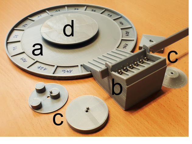
We developed a 3D printable model for a mechanical scattering experiment with 5 mm steel balls (ball bearings). This setup includes
- base (a): a circular base plate with a diameter of 18 cm and 16 pockets to collect the scattered steel balls
- ramp (b): a ramp for 7 steel balls of 5 mm diameter, with a distance of 7 mm. The beta version of the ramp provides 3 different starting positions at a different height to modify the kinetic energy of the steel balls
- scattering objects (c): including a circular cylinder (diameter 4 cm), triangular prism (side length 3.5 cm), 1/r potential hill (max. diameter 3.5 cm), cuboid (side length 3.5 cm) and an object with a substructure (3 small circular cylinders, each 1 cm in diameter)
- lid (d): can be attached to the scattering objects to hide them underneath
- steel balls (e): need to be purchased separately, diameter 5 mm, look for a shop selling ball bearings
All design files can be downloaded from Thingiverse.
Instructions
- Prepare all the material needed and 3D-print components.
- Place one of the scattering objects on the base plate and cover it with the lid.
- Attach the ramp to the base plate and place 7 steel balls.
- Let participants roll the steel balls one by one and ask them to observe how they scatter with the hidden object.
- Let participants draw their model of the inferred shape of the obstacle.
- Encourage participants to repeat and be as precise as possible, before comparing model to obstacle.
- Repeat this with different types of obstacles with increasing difficulty.
Ideas for educators
There are different ways to use this scattering model in your classroom. Depending on the age and level of your students, we propose 3 different difficulty levels. In any case, it is important to discuss the limits of this mechanical scattering model when comparing it to the goal-foil experiment.
Qualitative approach
The scattering patterns are interpreted only qualitatively. Students get to see the different scattering objects beforehand. Then, one of the students or the teacher hides one of the objects under the lid. After observing the scattering angles for a few steel balls, students try to guess the shape of the hidden object. This activity can be used to highlight the difference between observation (the scattered steel balls) and inference (the conclusion we draw based on our observation, in this case, the shape of the scattering object) in science. However, in real life, we have no way of “lifting the lid” to confirm our hypotheses. Instead, we can only design new experiments to test our hypotheses. Here, the role of models in scientific research can be discussed. In this version of the activity, we suggest starting without the 1/r potential hill. In the end, the teacher can use the potential hill to highlight the difference between mechanical scattering objects and Coulomb scattering potentials.
Semi-quantitative approach
The qualitative approach can be extended by having students systematically record data and study the average scattering angles and scattering patterns in a diagram. To interpret the different scattering patterns, students don’t need to use formulae. Instead, the following argumentations can be used.
- Triangular prism: The scattering angle should be more or less the same for all steel balls because this angle only depends on the shape and orientation of the prism. Here, the angle of incidence = the angle of reflection.
- Circular cylinder: Again, the angle of incidence = the angle of reflection. However, the angle of incidence depends on the position of the steel ball relative to the centre of the cylinder. If a steel ball hits the cylinder only at the side, it will be deflected less.
- 1/r potential hill: The discussion is similar to the circular cylinder. However, the effective diameter of the 1/r potential hill is a bit smaller, which lead to a more narrow scattering pattern. Also, the scattering angle depends on the energy of the steel ball. Steel balls with higher kinetic energy will roll higher up onto the potential hill. Therefore, they will effectively hit a “smaller” scattering object there, because the radius of the potential hill decreases with height. This effect can also be used to discuss the need for high-energy projectile particles in high-energy physics. For example, if scientists are interested in studying the substructure of atomic nuclei, the energy of the projectile particles needs to be high enough to overcome the Coulomb potential of the nucleus. Only then will the projectile particles reach the area of the strong nuclear forces.
Quantitative approach
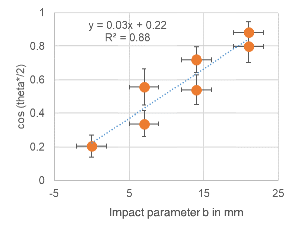
This activity can be extended even more if students compare their empiric data with the theoretical predictions. For example, students can try to confirm the relationship between the scattering angle (theta) and the impact parameter (b) for the circular cylinder b~cos (theta/2). Moreover, students can study the energy dependence of the scattering angle for the 1/r potential hill. Students can also compare their results with the results of the gold-foil experiment and try to understand how Rutherford derived an upper threshold for the radius of atoms based on the results. Finally, students can record and analyse the hyperbolic trajectories, for example, using smartphones apps such as Motion Shot.