ATLAS Magnet Model
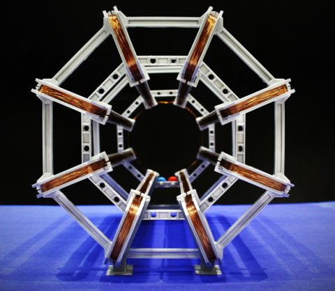
Build a model of the toroidal ATLAS magnet system using simple materials or a 3D printer.
The ATLAS detector, the largest particle detector at the LHC, is one of the most complex machines ever built. But how do you explain such complexity to students? This hands-on activity provides a creative way to explore the ATLAS toroidal magnet system by building a model from everyday or 3D-printed components. It opens powerful opportunities to discuss electromagnetism, particle detection and the role of models in physics.
At 25.3 m in length, the central toroid of the ATLAS detector is the largest toroidal magnet ever constructed. It is unique in particle physics and an iconic element of ATLAS. You can learn more about its function and significance in the ATLAS experiment here.
Page Overview
Cardboard and Straw Version
Material List
-
Print-outs of the 2D templates for A3 printing (red and blue templates). You can find them here.
- Drinking straws (approx. Ø 8 mm, 22 cm long)
- Enamelled copper wire (Ø 1 mm, 30 m length) - 7 turns per coil
- Cardboard (approx. 25 cm x 50 cm)
- Cutter
- Pliers
- Lighter
- Ruler
- Sandpaper to remove the enamel layer (optional)
- Adhesive tape
- Glue
- Soldering iron and solder (optional)
- 2 x 4 mm banana sockets
- Experiment cables with 4 mm banana plugs
- Power supply (12 V DC) or battery pack
- Multimeter (optional)
Instructions
To Build
- Print the red template on A3 paper and glue it to a piece of cardboard.
- Use adhesive tape to attach a straw along each long side of the template
- Wrap enamelled copper wire around the straws to create a coil with 7 turns (approx. 3.5 m of wire), leaving about 10 cm of wire free on each end.
- Repeat this process eight times to create eight coils.
- Print the blue template twice on A3 paper and glue each to a piece of cardboard.
- Cut out all the white sections from the blue templates using a cutter to create support structures.
- Insert the eight coils into the slots of the support structures, making sure all wire ends are on the same side.
- Use stronger cardboard or double up cut-outs if the structure feels too flimsy (optional).
- Strip the enamel from the ends of each wire using sandpaper or a lighter.
- Twist the outer wire of one coil to the inner wire of the next coil. Continue until only two free ends remain.
- Solder the twisted wire ends together for better connectivity (optional).
To Operate
- Connect the two remaining coil ends to a 12 V DC power supply or battery pack using banana plugs and sockets.
- Observe the magnetic field using a compass, 3D compass or a smartphone app such as a MagnetMeter.
3D-Printed Version
Material List
-
3D printed parts: 8 coil frames, 16 inner struts, 16 outer struts, and 4 feet. Download all files from here.
- Cyanoacrylate glue (super glue)
- Cutter
- Pliers
- Lighter
- Enamelled copper wire (Ø 0.5 mm, 500 m length)
- Soldering iron and solder
- 2 x 4 mm banana sockets
- Experiment cables with 4 mm banana plugs
- Power supply (12 V DC) or battery pack
- Multimeter (optional)
- Sandpaper to remove the enamel layer (optional)
Instructions
To Build
- Download and 3D print the required parts.
- Assemble the printed parts using cyanoacrylate glue (super glue).
- Strip the enamel from the ends of the wire using a lighter or sandpaper.
- Wrap enamelled copper wire (Ø 0.5 mm) around each coil frame to create 80 turns per coil.
- Connect the coils by soldering the wire ends together.
- Ensure that two wire ends remain free to connect to the power supply.
To Operate
- Connect the two remaining coil ends to a 12 V DC power supply or battery pack using banana plugs and sockets.
- Observe the magnetic field using a compass, 3D compass or a smartphone app such as a MagnetMeter.
Simplified 3D-Printed Version
Material List
-
3D printed parts: Front coil support, rear coil supports, 8 coil frames. Download all files from here.
- Cutter
- Pliers
- Lighter
- Enamelled copper wire (Ø 0.5 mm, 500 m length)
- Soldering iron and solder
- 2 x 4 mm banana sockets
- Experiment cables with 4 mm banana plugs
- Power supply (12 V DC) or battery pack
Instructions
To Build
- Download and 3D print the required parts.
- Assemble the printed parts. This version is more robust and does not require gluing.
- Strip the enamel from the ends of the wire using a lighter or sandpaper.
- Wrap enamelled copper wire (Ø 0.5 mm) around each coil frame to create 80 turns per coil.
- Connect the coils by soldering the wire ends together.
- Ensure that two wire ends remain free to connect to the power supply.
To Operate
- Connect the two remaining coil ends to a 12 V DC power supply or battery pack using banana plugs and sockets.
- Observe the magnetic field using a compass, 3D compass or a smartphone app such as a MagnetMeter.
- This activity must always be performed under adult supervision.
- Only use low-voltage power supplies (e.g. 12 V DC) — never connect the coils to mains electricity.
- Use tools like soldering irons, cutters and lighters with great care to avoid injury or burns.
- Handle all wires and connections safely to prevent short circuits.
- If you are using a battery pack, make sure it is secure, insulated, and suitable for the experiment.
Ideas For Educators
- The article "A Functional 3D-Printable Magnet Model of the ATLAS Toroid" contains a more detail description of the project, together with several ideas for educators. Click here to read the paper.
- For high school students, we recommend a stepwise assembly process, accompanied by exploration and guided discussion.
- For the assembly, a pair of students can first make one coil, connect it to a power supply and then explore the magnetic field of their coil. Magnetic field lines can help to visualise the field and can be drawn with the help of compasses or other probes such as 3D compasses or smartphone apps such as MagnetMeter.
- Subsequently, students connect a second coil and study the superposition of the two magnetic fields.
- Compare the model toroid with the real ATLAS toroid. Use this comparison to discuss the role of models in physics.